AFA calculates a graphic network map that includes the devices in the system, as well as the networks and routers that are directly connected to them. This map is automatically updated each time a device is added or deleted, or when AFA collects a routing table that has been modified.
AFA uses the graphic network map when running traffic simulation queries on groups; therefore, it is important to ensure that the map is correct and that it includes all relevant network elements (especially routers). If necessary, you can modify the graphic network map to better reflect the network architecture.
For more details, see Modify the graphic network map.
Note: From the network map, you can run a routing query to see the devices in the path without policy simulation. For details, see Run a routing query
Network map elements
|
Element |
Description |
|---|---|
|
A device icon |
A device defined in AFA. The device's name appears under the icon. Hover over to view the device name, brand, and IP address. |
|
|
A transit network. A network which passes traffic between other networks. The network's name or CIDR is displayed under the icon. |
|
|
A computer network. A network connected to a single host. The network's name or CIDR is displayed under the icon. |
|
|
A router. A device with an interface that was discovered as a next-hop in a routing table. The router's IP address is displayed under the icon. Hover over to view the names of the devices that route to the router. |
|
|
A cloud. All addresses routed through a discovered router. Hover over to view the cloud IP address or address ranges. |
|
|
An IPsec tunnel. A virtual communication channel between two networks.
Hover over to view the tunnel's CIDR. |
|
|
A routing element. A generic device defined in AFA with only SNMP credentials. Performs SNMP connections for retrieving routing tables without collecting configurations. |
|
|
An MPLS tunnel.
Hover over to view the tunnel's CIDR and route target. |
|
|
A layer 2 subnet. A subnet (transit network or computer network) with more than one layer 2 devices placed in it. For more details, see Manage Layer 2 (L2) devices in the map. Hover over to view the list of L2 devices in the subnet. |
|
|
A layer 2 device. A layer two device placed in a subnet (transit network or computer network). For more details, see Manage Layer 2 (L2) devices in the map. |
|
|
A router that was created by merging more than one router in the graphic network map. |
|
|
An edge. This can be either of the following:
|


View the network map
AFA's graphic network map displays all of the elements in your ASMS environment. You can move elements around and zoom in and out as needed. Hover over elements for more details or right-click to open the context menu.
Note: When right-clicking on an element, the context menu includes different options based on the type of device selected.
Do the following:
-
View the device, group, or matrix you want to zoom in on. For details, see View AFA device data, View AFA group data, and View AFA matrix data.
-
Click the Map tab.
The Map tab appears in the workspace.

All of your devices are shown in the map, but the map centers on the device, group, or matrix you selected.
Note: Management devices are not displayed in the map. Instead, the map shows each individual device, even if it's managed by a management device.
-
Do any of the following:
- Zoom and pan on the map
- Bring connected elements closer on the network map
- Search for a specific object
- Show or a hide the Legend
- View information about a specific map element
- View ranges of a cloud element
- View a connectivity diagram
- View a latest report
- View a device's route to a specific IP address
- View a device's routing information
- Show or hide a device's neighborhood
Note: A score for the completeness of the network map appears at the bottom of the map. For more details, see Modify the graphic network map
Zoom and pan on the map
Do any of the following to zoom in or out or pan across the map:
|
Zoom in or out
|
|
| Resize to fit | To resize the graphic network map to fit the screen, click  . . |
|
Pan across the screen
|
On the direction control button, click the arrow pointing in the direction you want to take. If the cursor is not in Pan mode, switch by clicking |

 or
or  on the zoom bar.
 . Then, click the map and drag it in the desired direction.
Bring connected elements closer on the network map
Two connected elements in the network map (like devices, routers, and subnets) can sometimes be too far apart to see at one time on the screen. Instead of trying to zoom and pan each time you want to see what's at the other end of a connection line, you can:
- Double-click the connection line between two elements to bring them closer together.
-
Double-click the line again to toggle elements back to their previous position.

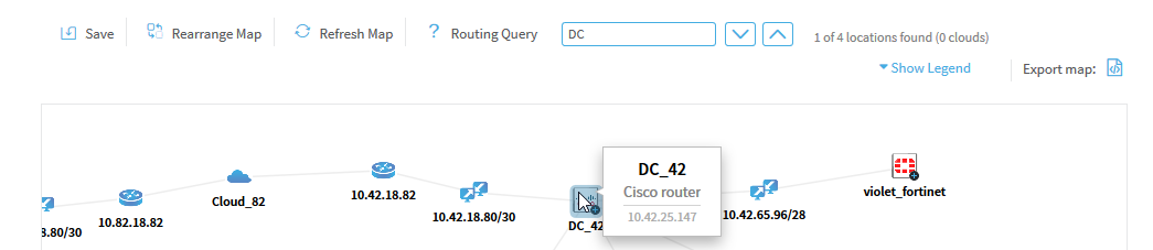
Search for a specific object
To search for an IP address, range, CIDR, or node name, including devices, subnets, routers, or clouds, in the graphic network map, see Search the map.
Show or a hide the Legend
To view the map element legend, select Show Legend from the context menu. Click Hide Legend to hide it again.
For more details, see Network map elements.
View information about a specific map element
To view information about a specific map element (if available), do the following:
Hover over the element. If there's any details available, a tooltip appears displaying the information.
For example:
For more details, see Network map elements.
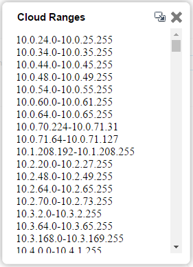
View ranges of a cloud element
If the element is a cloud, and the tooltip states that additional information is available, either double-click the cloud, or right-click the cloud and select View Ranges from the context menu.
The Cloud Ranges window appears displaying the cloud's IP address ranges.
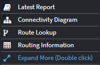
View a connectivity diagram
To view a device's connectivity diagram, right-click on the device and select Connectivity Diagram from the context menu.
The connectivity diagram opens in the new window.
View a latest report
To view a device's latest report, right-click on the device and select Latest Report from the context menu.
The latest report opens in the new window. For more details, see View AFA device data.
View a device's route to a specific IP address
To view a device's route to a specific IP address, do the following:
-
Right-click on the device and select Route Lookup from the context menu.
-
In the Route Lookup dialog, enter the IP address you want to view the route to.
One of the following occurs:
- The route to the IP address appears on the map in blue.
- If the destination is unreachable, the problematic device is boxed in red, and a pop-up describes the problem.
View a device's routing information
To view a device's routing information, right-click on the device and select Routing information from the context menu.
The routing information appears in a new window.
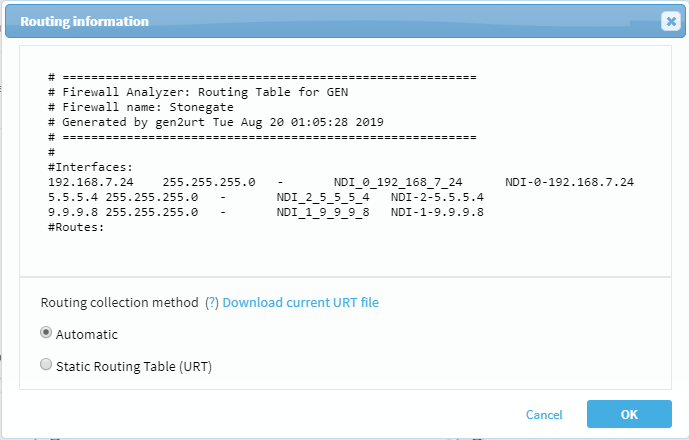
For details on how administrators can manually specify routing data, see Specify routing data manually.
Show or hide a device's neighborhood
A device's neighborhood includes network map elements that do not connect two devices, but whose existence is inferred from the device definition.
- To show a device's neighborhood, double-click the device, or right-click and select Expand More from the context menu.
- To hide the neighborhood, double-click the device again, or right-click and select Collapse from the context menu.
- To return to the default view, double-click the device or right-click and select Expand from the context menu.
For more details, see Network map elements.
Note: Selecting a device automatically selects its entire neighborhood.
Hidden elements will be exposed in the map they are relevant to a search or Route Lookup.
Host-based devices in the map
Public cloud devices, including AWS and Azure devices, appear in the map as all of their internal network elements:
- The network elements that make up the AWS account or Azure subscription will appear in the map as individual icons, and traffic simulation queries benefit from the routing information within the system.
- The network elements represented in the map include VPC / VNET routers, VPC / VNET peerings, internet gateways, VPN gateways and more.
-
Cloud subnets contain cloud assets (EC2 instances, VMs etc.) protected by Security Groups (SGs, NSGs). When you click a relevant Security Set in the device tree (a set of 1 or more SGs), the map will be focused on the subnet containing the cloud assets protected by this Security Set.
Note: VMware NSX network elements do not appear in the graphic network map.
Search the map
To search the Graphic Network Map:
-
In the text box above the map, type the IP address, subnet or device name you want to search for, then press Enter.
The first occurrence of the search input is selected in the network map. The total number of occurrences and the number of occurrences that are clouds are specified.
If multiple occurrences are clouds, the Merge Clouds link appears, enabling you to easily merge any or all of the clouds. For more information on merging clouds, see Merge multiple clouds.

- To view the next occurrence of the search input, click
 .
. - To view the previous occurrence of the search input, click
 .
.
Export the map to Visio
You can export the graphic network map to the *.svg format, which can be read by Microsoft Visio.
To export the graphic network map to Visio:
- View the graphic network map. For details, see View the network map.
-
Click
 .
.The graphic network map is exported to an *.svg file and can be opened and/or saved to your computer.